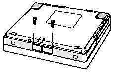
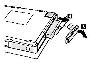
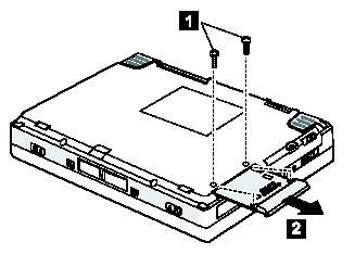
Actions: (If applicable:) Remove the two security screws locking the eject levers.
Tools: 2.5mm Allen wrench.
Notes: Most users do not have these security screws in place.
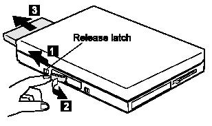
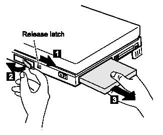
Actions: Remove the battery pack, and the UltraBay II device, and the hard drive.
Tools: Coin (for hard drive security screw, if present).
-
Remove the battery pack.
-
Remove the UltraBay II device.
-
Remove the hard drive.
Actions: (If applicable:) Remove the DVD and Enhanced Video Adapter (DEVA):
Tools: Small Phillips screwdriver
Materials: 2 x 6mm screws
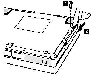
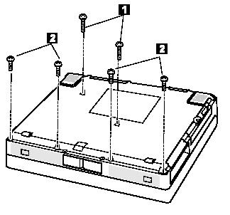
Actions: Remove the 6 visible screws from the bottom of the laptop case: 2 in the centre area, and 4 in a row along the front of the case. [+one more? for motherboard removal later?]
Tools: Small Phillips screwdriver
Materials: 2 x 8mm screws [Number 1 in Figure F below], 4 x 6mm screws [Number 2 in Figure F below]
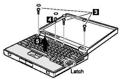
Actions: Turn the laptop upright, open the lid and remove the 4 screw covers and screws from the rear of the keyboard where the keyboard meets the LCD. The screw covers can be removed by carefully prying them up with a needle or Xacto knife. Note that one of these 4 screws is shorter than the others [Number 4 in Figure G below] -- you will have to remember to screw the short one back in the same spot during reassembly.
Tools: Small Phillips screwdriver, Xacto knife (or needle)
Materials: 3 x 8mm screws [Number 3 in Figure G below], 1 x 4mm screw [Number 4 in Figure G below]
Actions: Lift up the keyboard by simultaneously pushing both lid latches back towards the rear of the machine while using your thumbs to push up on the front edges of the keyboard. The "latch" in the diagram above is simply a tiny lip edge or "tang". There are a pair of other "tangs" or lip edges at the rear of the keyboard which I find more difficult to free than the "latch" on the side. You may need to wiggle the keyboard slightly side to side to free it from the tangs holding it in place at the rear. Do not try to lift the keyboard completely off as it will still be attached on the bottom by some fragile ribbons in the left rear [see Figure H below]. Tilt the keyboard up gently from the front until you can see the ribbons underneath.
Tools: None
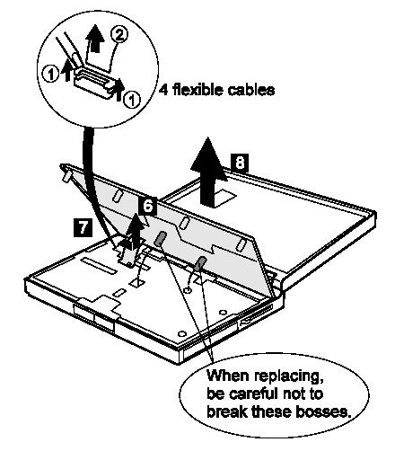
Actions: This is one of the awkward steps. There are 5 ribbons (flexible cables) connecting the bottom of the keyboard to the base of the ThinkPad beneath it. 4 of these ribbons carry data, and one is just a plain clear plastic ribbon whose purpose is simply to prevent you from accidentally damaging the other ribbons by pulling the keyboard too far up. The clear plastic connector ribbon is attached to a black clip. This clip can simply be slid to the right to unhook it from the base while leaving the ribbon attached to the clip [Number 6 in Figure H above]. Now, using your fingernail, or the edge of a small screwdriver, lift the left and right edges [Numbers 1 in Figure H above] of each of the ribbon connectors. Once both edges of a connector are lifted enough (just a millimeter or two) to unlock the ribbons, the ribbons will slip out of the sockets without forcing them [Number 2 in Figure H above]. Then you can lift the keyboard entirely free of the base. -- once you get the two out that are closest to the front -- the ones with the green ribbons, then you can open the keyboard up wider to get at the smaller ones with the bronze/gold ribons)
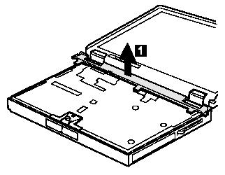
Actions: Remove the black plastic strip or "center cover" [Number 1 in Figure J below] across the top of the keyboard area. You might have to wiggle it a bit but it should not be attached to anything.
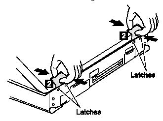
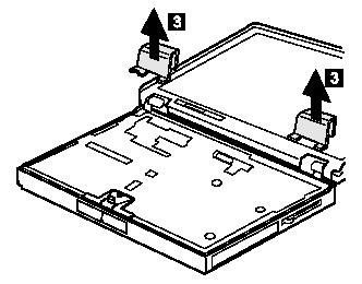
Actions: Remove the 2 hinge covers by almost closing the laptop lid and then squeezing the hinges to release the two "latches" that hold each hinge onto the base [Number 2 in Figure K-1 below], then open the lid back up completely and pull the two hinge covers out completely [Number 3 in Figure K-2 below]. Sometimes the hinges seem to get stuck on something when I'm opening the lid back up during this step, but you should be able to just squeeze and wiggle them out with some care.
Actions: Remove the power switch on the left side of the machine. You should be able to just pull it up and out without any tools.
Actions: Remove the tiny LED card for the UltraBay eject mechanism at the front of the machine. It is held in by a tiny clasp/tang on one side of the top. You should be able to just gently free it from the clasp and pull this out without any tools. Unwind the LED wires from the black clip. Note carefully exactly how the wires are threaded through the clasp so that you will be able to replace it easily on reassembly.
Actions: Remove the screw on top of the clip that holds the battery/floppy/CD release levers.
Actions: Unclip the speakder wires from the various clips and holders but leave them still attached to the speakers. Pay careful attention to how they are threaded so that you will be able to thread them correctly later. Pull the speakers up and out of the base and lay them beside the laptop, still attached.
Actions: Lift the lever clip straight up and out slowly. Remove the levers (open both releases then wiggle them out, first left side, then right side -- you will have to rotate the right side lever around to get it out as it has an edge on its bottom that will catch on the frame on the way out - the lever clip should then wiggle free.
Actions: Look down the top of the silver cover at all the holes and remove all the screws that you can see through holes in the metal shield: you should see five of them: 2 by the backup battery and two by the UltraBay opening on the side and one slightly the longer one close to the front centre. Also, remove the single screw in the center of the black plastic thingy at the back. If you use the exact right size screwdriver, the screws will often stay gripped to the tip when you pull them out, but I invariably still lose a couple in the body and have to shake them out of the side openings or flip the laptop over and shake them out (gently!)
[This step is not necessary - just need to remove the screw underneath, which is noted above] the backup battery can just be pulled out of the way. Remove the backup battery(left edge, thin, usually green with wires), one screw is underneath or beside it, depending on how it is sitting.
Actions: Remove the single screw holding the LCD cable on the right rear. Pull up both LCD cables.
Actions: Position the LCD panel straight upright and remove the 4 LCD screws from the back of the machine. As you remove these screws, gently hold onto the LCD panel to support it. Pull out the LCD panel entirely.
Actions: Remove additional screws from the back of the machine: the 2 from the floppy port(very small black screws) and 2 from the USB port.
Actions: Unscrew the strange black thingy with three screws in a row. This is the last thing holding the heat shield in place. You can try just unscrewing the middle (silver) screw. The other two are not holding it inplace.
Actions: Pull out the Heat Shield carefully and slowly. The speaker wire may be wound around a flexible plastic clasp on the bottom: you will have to unclasp that wire before the heat shield will come away completely freely.
Actions: Remove more screws from the back: 2 from the serial port(the hex shaped studs) [5mm hex] , and 1 from below the PS/2 mouse port. (these hold in the DC-DC Card)
Actions: Remove two screws holding in the fan.
Actions: Remove 3 screws holding in the DC-DC card. For some reason, these screws seem more likely to be stuck or siezed than any other screws on these Thinkpads.
Actions: Pull the microphone and spacer up to free it from the board, without pulling too hard on the cable it is attached to.
Actions: Gently pull up on the DC-DC card using the white plastic "pullers". You should be able to pull the fan out at the same time, leaving it attached to the DC-DC card, and setting them both aside, together. If not, you will have to release the fan cable from the DC-DC card and remove the fan separately.
Actions: Remove the three screws holding the video card. Pull the video card up and out using the white "puller".
??2 from the VGA port. [don't need to remove VGA port studs, only serial port--they are attached to DC-CD card. VGA port is attached to video card. - NO.]
[After all the hold down screws have been removed, 2 under CD slot, 1 or 2 just aft of CD slot; 2-3 in very front, center; 2-3 on left side(under backup battery) lift the silver RF cover off the laptop.]]??
Actions: Remove screws from CPU fan, CD board(just to left of fan), and video card(just in front of fan)
Actions: Remove screws from heat sink(2), remove screws from CPU card(3) an CAREFULLY lift BOTH edges of CPU card, DONT lift up on left side without equal lifting on right side which is where the connector is (bend the connector fingers and you're done)
Actions: Remove the old CPU card and replace with the new one. Evenly apply pressure to right side of CPU to seat the card in the slots.
